About the report
Following the adoption of the CO₂ Storage Directive, Carbon Management Europe (then known as the Zero Emissions Platform) published this report to advise the Commission on research and development (R&D) funding priorities.
At the time, the European Union (EU) was leading the world in implementing an ambitious demonstration programme for carbon capture and storage (CCS) as a critical technology for combating climate change. The goal was to ensure that CCS became commercially viable by 2020.
The report highlighted that, while individual components of the CCS value chain had already been proven and were ready for scale-up and integration, further R&D into next-generation technologies needed to begin immediately to enable rapid and widespread deployment beyond 2020. It outlined key areas for improvement, together with the main strands of R&D through to 2030 and beyond.
1. Introduction
1.1 Background and purpose of this document
In October 2006, reports were published by ZEP Working Groups on Power Plant and CO2 Capture Technology and CO2 Use and Storage, respectively. The goal: to identify first-generation CO2 capture technologies and R&D needed to validate and demonstrate CO2 storage in order to commercialise power production with CO2 Capture and Storage (CCS) by 2020. Capture technologies likely to reach maturity beyond this date were also briefly mentioned.
These reports provided input into the ZEP Strategic Research Agenda (SRA), in which the following key recommendations were made:
- Urgently implement 10-12 integrated, large-scale CCS demonstration projects Europe-wide
- Develop new concepts already identified, but not validated, for demonstration by 2010-2015 and implementation beyond 2020
- Support long-term R&D into advanced, innovative concepts for implementation of next-generation technology
- Maximise cooperation at national, European and international level
- Strengthen and accelerate R&D priorities to support the Strategic Deployment Document (SDD), informed by experience from demonstration projects and parallel R&D projects on advanced, innovative concepts.
In April 2007, using the SRA and the underlying Working Group reports as a starting point, ZEP Taskforce Technology then published a report elaborating on their recommendations for RTD, support actions and priorities in the FP7 Energy Work programme and National RTD Programmes. This report was further developed and updated in April 2008.
CO2 capture
In parallel with the commercial introduction of first-generation CO2 capture technologies – supported by point 1 above – one obvious way forward is to search for improvements in these technologies, primarily in terms of efficiency and cost. Other areas of improvement may include reliability, availability, maintainability and flexibility (e.g. in terms of fuel or operation).
However, such incremental improvements are not likely to be sufficient to meet the requirements of CO2 emissions reduction in an energy- and cost-efficient way. The vision of ZEP is to ensure that CCS is deployed to its fullest potential and reduce CO2 emissions in the EU by over 50 per cent. Thus, technologies developed under points 2 and 3 must contribute to the future portfolio of CCS and R&D in these areas and be further specified.
CO2 storage
Knowledge and experience gained through industrial and academic research at laboratory and field scale at CO2 storage test sites and industrial pilots worldwide have shown that it is both viable and secure, making CCS a key carbon mitigation technology.
Currently available technologies and methodologies already cover critical elements in the design and management of the CO2 transport and storage value chain. The focus of current and near-term RTD is therefore validation of the technology and confirmation of our understanding of subsurface processes through a combination of monitoring and modelling methodologies.
From demonstration to deployment
But wide deployment of CCS in Europe will require the implementation of hundreds of commercial projects, at scales often several orders of magnitude larger than existing pilot projects. It is therefore essential to develop methodologies that will ensure the efficient and safe management of large CO2 storage sites in wider regions, on- and offshore.
Developing mitigation and remediation plans, should CO2 migrate outside the originally perceived storage site boundaries, will also be more relevant and important for larger volumes of CO2 stored. While monitoring activities have so far aimed at verifying the fate of CO2 stored, the objective of future monitoring schemes will also be to focus on the effects of CO2 storage on reservoir behaviour at regional scale, as well as potential environmental impacts. Understanding these phenomena will be a prerequisite for the management of large-scale CO2 storage facilities.
The purpose of this document is therefore to identify RTD urgently required in order to enable the rapid and wide deployment of CCS post-2020:
- Highlight areas for improvement and related R&D needs, plus recommended main strands for further research within CO2 capture technologies with a long-term perspective
- Provide a structured presentation and brief discussion of the technologies / methodologies expected to facilitate CO2 storage deployment from the demonstration phase to rapid and wide deployment.
This report presents a compilation of identified long-term perspective R&D needs for CO2 capture technologies known today. However, novel technologies – or the novel use of known technologies – are not unlikely to be presented in the years to come. It is therefore vital that future research programmes are formulated in such a way as to include these novel technologies so they are given a fair evaluation. Novel technologies must not only offer the advantage of being advanced and innovative, but also have the potential for improvements compared to first-generation capture technologies, primarily in terms of breakthroughs in cost and efficiency.
Storage is an essential component of the CCS chain and provides critical considerations in the CCS decision-making process and planning. The experience and knowledge generated through existing and planned demonstration projects until 2020 will serve to inform decisions and reflect upon the technologies and methodologies proposed.
Conclusion
In conclusion, R&D in identified areas must be initiated and/or continued immediately, and in the years to come, to reach estimated maturity at the defined time-scales. Considering the time steps for development (laboratory – pilot projects – semi-industrial – industrial – pre-commercial), continuity from the EU in supporting developing technologies is vital.
In this context, it is important to recognise the need for medium-sized pilot projects – which are risky and costly – and which are a limiting factor for new developments. For technologies still at an early stage, correct technology potential assessment may be difficult, because ‘showstoppers’ and sudden technology breakthroughs cannot be foreseen, but are the outcome of dedicated R&D.
1.2 Other related activities
CCS is a fast-growing industry and there is a good deal of work ongoing on mapping knowledge gaps and developing roadmaps for CCS R&D and deployment – including the work of ZEP.
For example, the Carbon Sequestration Leadership Forum (CSLF) delivered its technology roadmap in 2009 (www.cslforum.org). The International Energy Agency (IEA) has also followed up on the G81 call to have 20 operational projects by 2020 with a global CCS technology roadmap, which concludes that 100 commercial-scale CCS projects must be operational by 2020 to keep the increase in global temperature below 2°C – as agreed in the Copenhagen Accord (www.iea.org/Textbase/subjectqueries/cdcs.asp).
As CCS cannot be effectively deployed at a small scale or in small units, the key bottleneck to date has been to find a reasonable cost and risk sharing between industrial partners and governments – projects could easily cost €1-2 billion. We recognise that state, national and international governments are increasingly sponsoring demonstration and early commercial projects and CCS R&D activities.
This support is being deployed through a range of competitive selection processes that aim to build national capability and establish deployment expertise. The programme outlined in this document would therefore be enhanced by establishing synergies with other national and international programmes through the EU / ZEP Knowledge Sharing Framework.
1.3 Applications to other industries
This report does not aim to cover the R&D needs of CCS deployment for industries other than the power sector. However, in order to identify and explore synergies with other industries, such as oil and gas, steel, metallurgical, cement, petrochemicals, etc., a joint task force will be formed to develop a separate document. This issue is also addressed in the IEA roadmap.
The Zero Emissions Platform (ZEP)
The European Technology Platform for Zero Emission Fossil Fuel Power Plants (ZEP) – otherwise known as the Zero Emissions Platform – is a broad coalition of stakeholders united in their support for CCS and its leading authority in Europe. Members include European utilities, petroleum companies, equipment suppliers, national geological surveys, academic institutions and environmental NGOs.
This report has been developed by over 70 CCS experts from two ZEP Working Groups within ZEP Taskforce Technology: Long-term R&D Plan for Capture Technology and Long-Term R&D Plan for Storage and Transport Technology.
2. CO2 Capture
2.1 Time and technology structure
2.1.1 Timeframe definition
The timeframe for long term R&D has been categorised within the following intervals, corresponding to the periods where the R&D efforts performed now and in the years to come will result in commercially available technologies:
- Period I, up to 2020: Medium term, not subject for this document but provided for establishing a baseline and likely development.
- Period II, 2020-2030: Technologies brought to commercial operation within this period are likely to be based on improvements and refinements of technologies employed in Period I. Some new technologies, today in the R&D phase, should reach the demonstration or even the commercial phase.
- Period III, 2030 and beyond: Long-term technologies. Technologies brought to commercial operation within this period are likely to be based on optimised and refined technologies from periods I and II. In particular, demonstration phase technologies from Phase II should become commercial. New technologies, which today could be in R&D infancy, should reach the demonstration phase and then become commercially available.
2.1.2 Capture routes and technology blocks
Table 1 below gives an overview of the “technology blocks” within each of the three main capture routes.
This is in accordance with the ZEP document “ZEP Matrix of Technologies” from October 2008, although the structure has been slightly rearranged.
Technology blocks that are specific to one of the three CO2 capture routes are in bold letters, and the long-term perspective R&D needs for these blocks will be further described in chapters 2.2 to 2.4.
Technology blocks that are not directly linked to only one CO2 capture technology, such as “CO2 compression”, are not in bold letters in Table 1 and are dealt with in Chapter 2.5. This is also the case for technology blocks that are not CO2 capture specific but more generally related to power plant improvements (e.g. 700°C steam cycle).
Table 1: Technology blocks (according to ZEP document: CO2 Capture and Storage (CCS) – Matrix of Technologies, October 15th 2008)
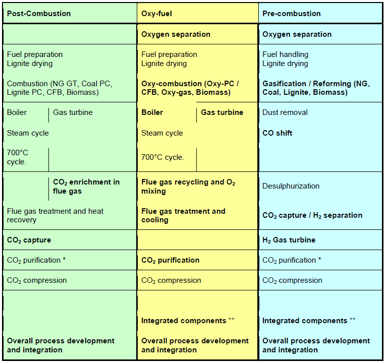
* For processes where the CO2 stream formed contains co-adsorbates and/or other impurities that can not be sequestrated with the CO2, further processing will be necessary. Specific separation steps taking care of this might therefore give rise to R&D activities where the aim is to modify existing processes or develop new specific separation processes.
** Two or more components/sub-processes integrated into one unit. Examples are CLC in the oxy-fuel route combining oxygen separation and combustion, and sorption enhanced reforming/gasification in the pre-combustion route combining gasification/reforming, water gas shift and CO2 removal
2.1.3 Validation status definition
In the coming chapters summary tables are provided where colour coding has been used to define the validation status for the different technologies under each technology block. As in the ZEP document “ZEP Matrix of technologies”, validation status is divided into three levels:
- Red Not validated: Not tested / Less advanced than pilot scale
- Yellow Partly validated: Ready for demo plant (a few 100s of MWel, depending on technology)
- Green Fully validated: Commercially available for application in large power plants.
In addition, shadings are employed between red / yellow and yellow / green where this is the most
appropriate.
2.2 Post-Combustion technologies
2.2.1 CO2 capture in Post-Combustion applications
Post-combustion capture technologies can in principle be applied to flue gases from all kinds of industrial processes, in particular power production from fossil fuels and biomass, cement, steel and aluminium production. Several separation principles are relevant. Absorption based on liquid chemical solvents (amines) is currently the leading and most developed technology. Further along the timeline other technologies such as adsorption by solid sorbents and high temperature carbonate looping cycles, membrane separation, cryogenic separation and use of biotechnology are seen as potential candidates.
Key challenges and long term R&D targets
- The high energy requirement of the separation process, a penalty of about 10 per cent in efficiency loss with present technology (MEA). A long-term R&D target (beyond 2030) should be to reduce this to below 5 percentage points.
- The low CO2 partial pressure (especially for NG power plants) and the large flue gas volumes imply very large equipment volumes and contacting surfaces. Long term R&D target: Reduce equipment volumes by developing more effective contacting surfaces
- Flue gas impurities (depending on fuel). Long-term R&D target: Develop capture processes independent from or at least very robust with respect to the composition of impurities in the flue gas. Develop capture processes which can efficiently co-capture impurities of larger concentration (like SO2)
- Degradation and environmental aspects. Long term R&D target: Develop processes with very low overall emission levels (including e.g. degradation products) develop in line measurement techniques for very low concentrations.
- Material of construction. Long term R&D target: Develop lower cost materials of construction for capture plants.
R&D needs
- Liquid absorbents: Liquid solvents need to have a lower energy requirement for regeneration than today, be non-toxic and environmentally friendly. They should also be robust against flue gas impurities and have a low degradation rate. In order to decrease CAPEX and OPEX, technological development is also necessary on gas/liquid contactors (including membrane contactors). The search for this type of solvent is ongoing and progressing, but is likely to continue beyond 2020. Systems using additional effects like precipitation, pH swing, and liquid extraction are likely to be an important part of the progress. Adaptation of capture and power process configurations is necessary to make the best use of these improved solvents.
- Solid sorbents: Sorption on solids (both low and high temperature sorbents should be considered) is an innovative way to reduce energy costs. New solids must be developed for Vacuum Swing Adsorption (VSA) and Temperature Swing Adsorption (TSA) processes with higher effectiveness and lower cost. Processes must be developed to match these solids.
- Vacuum swing adsorption processes (VSA / VPSA): Such processes are run in a similar manner as pressure swing adsorption (PSA) processes, but at much lower pressures and vacuum is needed to remove the CO2 in the desorption step. The challenge is to find good adsorbents with high cyclic capacity in the actual pressure range. Another challenge is to find adsorbents with high selectivity for CO2 in order to avoid accumulation of impurities that necessitate extra thermal regeneration of the adsorbent.
- Low temperature thermal swing adsorption processes: The biggest challenge when developing thermal swing adsorption processes for CO2 capture from flue gas is the low partial pressure of CO2 present that necessitate novel reactor design having low pressure drop over the adsorbent bed. To assure efficient heat transfer over the bed is also an issue.
- High temperature thermal swing carbonate looping processes, using, for example, CaO particles to react with CO2 are promising. The subsequent calcination of CaCO3 regenerates the CaO and returns high-purity CO2. R&D issues are: Scaling up of CFB carbonator and experimental validation at increasing scales, alternative calciner designs, and sorbent performance issues such as chemical and mechanical stability, integration of purge uses, combined SO2 capture, steam reactivation, etc.
- Membranes: The application of membranes in fossil fuel power plants requires large membranes that can be maintained and repaired. Moreover, it has to be considered that they have to withstand pollution, fouling as well as temperature and pressure changes. Properties that can not be delivered by today’s membrane technology. R&D needs: Development of cheaper and more robust membrane modules with high permeability and selectivity.
- Cryogenic technologies: Cryogenic liquefaction is feasible today, anti-sublimation process for CO2 separation is in the early demonstration phase.
- Generating hydrates for CO2 capture: R&D is needed to increase selectivity and kinetics.
- Materials of construction: R&D for lower cost solutions.
Summary table: Post combustion CO2 capture
(Colour codes: Green – validated, Yellow – partly validated, Red – not validated)
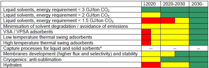
* Maturity will depend on the solvent or sorbent under consideration
2.2.2 CO2 enrichment in flue gas from gas turbines
The basic idea with this concept is to recirculate part of the flue gas from the gas turbine back to the compressor inlet, and thereby increase the CO2 concentration in the flue gas, which is beneficial to the post-combustion CO2 capture process. Also, concepts with oxygen-enriched air can be envisaged in order to produce flue gases with a further increase in CO2 concentration.
Key challenges and long term R&D targets
- Increase CO2 content in the flue gas in order to facilitate CO2 capture
- Stable and complete combustion in CO2-enriched atmosphere
- Stable and complete combustion in oxygen and CO2-enriched atmosphere
R&D needs
- Process configuration optimisation with recirculation of (part of) the flue gas prior to the CO2 capture unit
- Adaptation of gas turbines to operation with new CO2-enriched media, in particular to ensure stable and complete combustion
- Adaptation of gas turbines to operation with new oxygen and CO2-enriched media, in particular to ensure stable and complete combustion
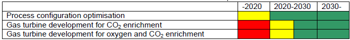
Summary table: CO2 enrichment in flue gas
(Colour codes: Green – validated, Yellow – partly validated, Red – not validated)
2.2.3 Overall process development and integration
Integration of the post-combustion capture process with the power generation process and the CO2 compression is a key point to reduce the energy penalty for post-combustion capture. Thus, this topic needs further attention. Furthermore, overall environmentally friendly integration of the power plant with respect to water consumption and pollutants is vital.
Key challenges and long term R&D targets
- Development of gas and solid fuel power processes with integrated post-combustion CO2 capture process, with maximised power output and minimum loss of waste heat, taking also into account good part-load performance.
R&D needs
- Minimization of overall energy penalty for flue gas cleaning and CO2 compression and intercooling
- Minimization of overall energy penalty for the steam cycle configuration with respect to CO2 capture and compression and good part-load performance
- Environmental integration of the power plant with respect to e.g. cooling water requirements, liquid effluents and their purifications
- Development and implementation of dynamic models to study transients in the power process as well as in the capture unit
Summary table: Overall process development and integration.
(Colour codes: Green – validated, Yellow – partly validated, Red – not validated)
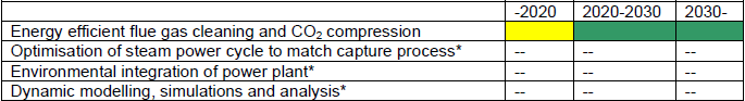
* Maturity depends on the capture process under consideration
2.3 Oxyfuel technologies
2.3.1 Oxygen production for oxyfuel applications
For the 1st large scale demonstrations (100s of MWth) of oxy-fuel power plants, and the first commercial generations, cryogenic air separation will be the only viable air separation technology due to the large scale. In longer time perspectives, other air separation technologies based on membranes or adsorbents are seen as potential candidates.
Key challenges and long term R&D targets
- Reduced energy consumption for oxygen production. Specific energy consumption of today's cryogenic processes is in the range 160 - 220 kWh/ton at ISO conditions2. A long-term R&D target should be to reduce this to the range 120 - 140 kWh/ton for improved cryogenic processes and down to the range 90 - 120 for membrane or sorbent-based technologies.
- Standardisation to reduce investment costs for cryogenic ASUs
- Adaption and optimisation of cryogenic air separation for the specific oxy-fuel boiler requirements.
R&D needs
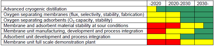
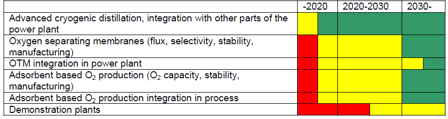
- Advanced cryogenic distillation technology, integration with other parts of the power plant or other
adjacent “cold industries” (e.g. LNG regasification) - High-temperature oxygen-separating membranes and adsorbents, which may have a potential for
efficiency improvement in oxyfuel operation compared to cryogenic ASU.
o Further materials development (flux, selectivity, improved performance at lower temperatures (below 700°C), industrial fabrication methods)
o Materials stability at sour conditions
o Further component development (membrane scale-up and manufacturing and adsorbent reactor design) and integration in power process.
o Pilot and full scale demonstration.
Summary table: Oxygen production for oxyfuel applications.
(Colour codes: Green – validated, Yellow – partly validated, Red – not validated)
2.3.2 Oxy-combustion
Extensive R&D is ongoing within Period I, to create a validated, firm basis for the design of oxy-fuel boilers to be used in large-scale demonstrations (100s of MWth) of oxy-fuel power plants. Validations and R&D is expected to continue also beyond the 1st demos. These first generation(s) of oxy-fuel boilers will operate at conditions similar to air-fired boilers. Selecting a higher O2 concentration for PF as well as CFB boilers provides potential for cost savings and efficiency improvements, but also requires entirely new boiler designs.
Research and demonstration is also ongoing on oxy-fuel gas turbine combustors, although to a smaller extent.
Key challenges and long term R&D targets
Oxy-fuel boilers
- R&D on corrosion, slagging and fouling in solid fuel oxyfuel PF and CFB boilers is ongoing within Period I, and is expected to continue also beyond the 1st demos
- Use the inherent potential for boiler size and cost reduction for PF and CFBs by enabling higher O2 concentrations and thus reduced flue gas recirculation
- Improved knowledge of sulphur chemistry for solid fuels
- Enhanced knowledge of the use of lean fuels (low-volatile coals, anthracite, petcoke)
- Improved CFD modelling is ongoing within Period I, and is expected to continue also beyond the 1st demos Oxy-fuel gas turbine combustors
- Oxyfuel gas turbine combustors: combustion and heat transfer
R&D needs
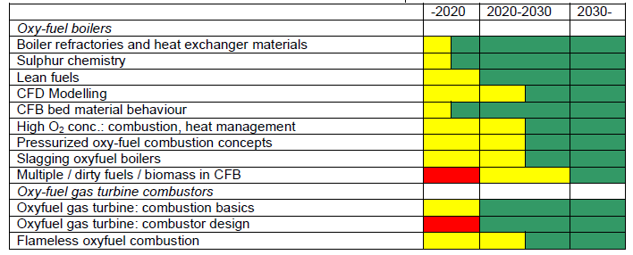
Oxy-fuel boilers
- Boiler heat exchanger and refractory materials: Issues of slagging, fouling and corrosion related to specific oxyfuel flue gas conditions need further investigation and long-lasting tests are ongoing and expected to continue also beyond 1st demos.
- Formation of various (gaseous) sulphur species (capturing in fly ash, SO3 formation, reduction of recycled SO2 / SO3) and direct desulphurisation without intermediate calcination step to be further investigated.
- Lean fuels (low-volatile coals, anthracite, petcoke) require special furnaces (down-shot, slag-tap) and/or special combustion technologies (indirect firing) for air combustion. Oxygen enrichment may offer the application of conventional direct PF combustion in conventionally shaped furnaces.
- CFD modelling (chemistry, interaction with CO2, radiation) is being adapted for oxy-combustion and validated within Period I, and expected to continue also beyond 1st demos
- CFB bed material behaviour: heat extraction from solid loop, in-situ sulphur removal is investigated in Period I
- PF and CFB boiler design for size and cost reduction with increased O2 concentration (i.e. less flue gas recycle). Development and tests in laboratory and in pilot plants of:
o Combustion characteristics in high O2 concentration.
o Design and heat managing schemes for high O2 concentration boilers. - Novel pressurized combustion concepts (with dry or wet coal feed) able to produce a concentrated, pressurized CO2 stream.
- Slagging oxyfuel boilers
- Operation with multiple / ”dirty” fuels / biomass in oxyfuel CFB and co-fired in oxy-fuel PF
Oxy-fuel gas turbine combustors
- Oxyfuel gas turbine combustors:
o Basic investigation of combustion of gaseous fuel with O2 in a CO2 and H2O environment under high pressure.
o Combustor design to enable complete and stable combustion of the fuel under altered (compared to air) heat transfer conditions. - Flameless oxyfuel combustion
Summary table: Oxyfuel combustion
(Colour codes: Green – validated, Yellow – partly validated, Red – not validated)
2.3.3 Oxyfuel gas turbine
The natural gas-fired oxyfuel gas turbine, operating with a CO2 / H2O mixture as working medium, and with recirculation of the main part of the working medium, can be designed from an aerodynamic point of view within current engineering practice. Research and development remain in terms of structural analysis and materials to be employed for construction, taking into account also the altered heat transfer conditions.
Key challenges and long term R&D targets
- Turbomachinery development, taking into account the altered heat transfer conditions in the hot parts
- Overall process design and control
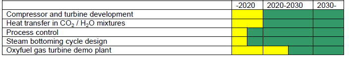
R&D needs
- Design of compressor and turbine for operation with a CO2 / H2O mixture as working medium
- Improved knowledge of heat transfer in turbines operating with an CO2 / H2O mixture, for design of new cooling schemes
- Design of control system for the semi-closed CO2 / H2O gas turbine with massive recirculation of the working medium.
- Development of steam bottoming cycle to match the gas turbine operating parameters
- Development of oxyfuel gas turbine demonstrator to improve the knowledge of the process
Summary table: Oxyfuel gas turbine
(Colour codes: Green – validated, Yellow – partly validated, Red – not validated)
2.3.4 Flue gas recycling and O2 mixing
Systems for mixing of oxygen and recycled flue gases are investigated and tested during Period I. Further improvements can be beneficial for combustion process control.
Key challenges and long term R&D targets
- Technologies and approved construction materials for safe mixing of oxygen and recycled flue gases that may contain dust and unburnt carbon
- Individual mixing points for O2 and recirculated flue gas (in burner, overfire, pulverizer)
- Corrosion reduction in the flue gas recycling duct
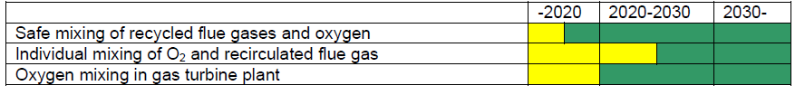
R&D needs
- Research and validation of technologies and approved construction materials for safe mixing of recycled flue gases and oxygen is ongoing in Period I and expected to continue.
- Individual mixing of O2 and recirculated flue gas may offer further possibilities to steer the ignition / pyrolysis / combustion process.
- Investigation of oxygen mixing in the gas turbine process
Summary table: Flue gas recycling and O2 mixing
(Colour codes: Green – validated, Yellow – partly validated, Red – not validated)
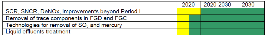
2.3.5 Flue gas treatment and cooling
R&D to adapt and validate by-product handling for specific oxy-fuel flue gas conditions is ongoing in Period I, and further improvements are expected beyond this period.
Key challenges and long-term R&D targets
- Improved handling of by-products in the oxyfuel generated CO2 stream
R&D needs
- Selective Catalytic Reduction (SCR), Selective Non-Catalytic Reduction (SNCR) for DeNOx: Due to specific oxyfuel flue gas conditions high-dust arrangements of SCR or SNCR-DeNOx plants need investigation of deactivation and S-conversion. NH3 and S related fouling and corrosion downstream the DeNOx plant might be an issue as well. These issues are investigated in Period I, and continued R&D on improvements is expected
- Removal of trace components in FGD and FGC
- Technologies for removal of SO3 and mercury
- Liquid effluents treatment and minimization.
Summary table: Flue gas treatment and cooling.
(Colour codes: Green – validated, Yellow – partly validated, Red – not validated)
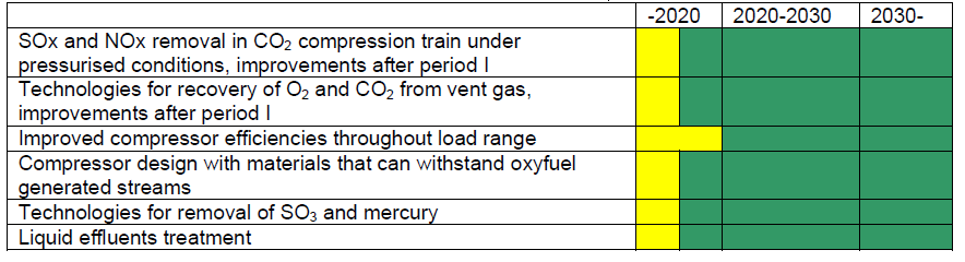
2.3.6 CO2 purification and compression
For oxyfuel, the CO2 stream at entrance of the compression and conditioning train can have high concentrations of components other than CO2. R&D to develop and adapt purification technologies for such conditions is ongoing within Period I, and further improvements are expected beyond this period.
Improved compressor performance at such conditions and throughout the entire load range would contribute to reduced energy consumption. It is noteworthy in this context that exact demands on the CO2 purity requirements imposed by transport and storage are currently unknown.
Key challenges and long-term R&D targets
- Refined handling of by-products in the oxyfuel generated CO2 stream remaining after the upstream cleaning steps
- Reduced compression energy consumption throughout the entire load range
R&D needs
- SOx and NOx removal in CO2 compression train under pressurised conditions is searched and validated in Period I and continued improvements are expected.
- Technologies for recovery of O2 and CO2 from vent gas are under development and continued improvements are expected.
- Improved CO2 compressor efficiencies at full load as well as part load and extended load range.
- Investigations of compressor materials to verify if they can withstand the composition of the oxyfuel generated stream
- Removal of trace components in FGD and FGC
- Technologies for removal of SO3 and mercury
- Liquid effluents treatment
Summary table: CO2 purification and compression.
(Colour codes: Green – validated, Yellow – partly validated, Red – not validated)
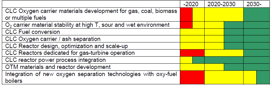
2.3.7 Integrated components (including CLC)
In this section, the oxygen membrane reactors and the chemical looping combustion (CLC) reactors are treated. In both cases, the separation of oxygen from air is integrated with fuel oxidation. CLC is under investigation in lab and pilot scales. There is a significant cost benefit due to (nearly) complete avoidance of the air separation unit. The fuel does not meet the air directly. The oxygen needed for combustion is supplied by an oxygen carrier material, which meets the fuel in the fuel reactor. This material is in the solid form and is recirculated from fuel to the air reactor. The reduced oxygen carrier is oxidised in the air reactor.
Key challenges and long term R&D targets
- Materials development (oxygen carrier material development for CLC, oxygen transport membranes)
- Reactor development with efficient fuel conversion
- Integration of the interconnected oxidizing and reducing reactors to achieve reliable operation
R&D needs
- Chemical Looping Combustion:
o Oxygen carriers (synthetically generated, naturally existing, oxygen capacity and kinetics,
mechanical and chemical stability, toxicity…).
o Development of various oxygen carriers for variable fuels (coal, gas, biomass, multiple fuels)
o Fuel conversion including avoidance of CO
o Validation and scale-up of oxygen carrier and ash separation
o Reactor design, structural optimization, and scale-up
o Use of advanced materials (e.g. ceramics, composites, etc.) in reactor design
o Scale-up
o Integration in power process
o Reactors dedicated for gas-turbine operation - Oxygen transport membrane (OTM) reactors: Materials development, reactor development, reactor
temperature control - Integration of new oxygen separation technologies (i.e. membranes and/or adsorbent processes) with oxy-fuel boilers.
Summary table: Integrated components
(Colour codes: Green – validated, Yellow – partly validated, Red – not validated)
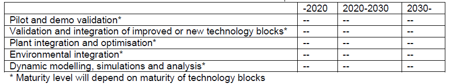
2.3.8 Overall process development and integration
For pilot, demo / full-scale testing of PF and CFB oxyfuel power plants (10’s to 100’s of MW), design for larger size plants is based on research findings from smaller scale in combination with findings from the sections listed above. As the knowledge of oxyfuel operation increases with the increasing number of plants, new possibilities for process integration will be easier to identify.
Key challenges and long term R&D targets
- Scale-up and validations of oxyfuel power plants with minimum energy penalty
R&D needs
- Validations in pilot plants followed by demos with associated R&D programmes
- New/improved technology blocks will require subsequent validations of integration issues in pilots and demos
- Plant integration and optimization for efficiency and cost, including part-load performance
- Environmental integration of the power plant with respect to e.g. cooling water requirements, liquid effluents and their purifications
- Development and implementation of dynamic models to study transients in the power process as well as in specific components
Summary table: Overall process development and integration.
(Colour codes: Green – validated, Yellow – partly validated, Red – not validated)
2.4 Pre-Combustion technologies
2.4.1 Oxygen production for pre-combustion applications
Currently for IGCC power plants, cryogenic air separation is the only viable air separation technology due to the large scale. In longer time perspectives, other air separation technologies based on membranes or adsorbents are seen as potential candidates.
Key challenges and long term R&D targets
- Reduced energy consumption for oxygen production. Specific energy consumption of today cryogenic processes is dependent on oxygen pressure and nitrogen integration (use of nitrogen in gas turbine). For oxygen at 4 MPa abs, the range is today 250 – 310 kWh/ton (at ISO conditions3) with nitrogen integration. Without integration it is 270 – 330 kWh/ton. A long term R&D target should be to reduce this specific energy by 40 kWh/ton for improved cryogenic processes.
- Further development of adsorbents and membranes for more energy- and cost-efficient oxygen production.
R&D needs
- Advanced cryogenic distillation, integration with other parts of the power plant or other adjacent “cold industries” (e.g. LNG plant)
- High-temperature – up to 300°C - oxygen separating membranes and adsorbents, which may have a
potential for efficiency improvement in IGCC (or IRCC) operation, compared to cryogenic ASU
o Membranes for O2 production: Membrane development (flux, selectivity, stability at sour conditions), manufacturing and scale-up methods.
o Membrane unit development for integration in IGCC power plant
o Adsorbent based O2 production: Adsorbent development (O2 capacity, stability at sour conditions), manufacturing methods.
o Adsorbent unit development for integration in IGCC power plant
o Pilot and full-scale demonstration
Summary table: Oxygen production for pre-combustion applications.
(Colour codes: Green – validated, Yellow – partly validated, Red – not validated)
2.4.2 Gasification / Reforming
Through the gasification of solid fuels or reforming of natural gas, a syngas consisting to a large extent of CO and H2 is obtained.
For solid fuels - coal, lignite as well as co-gasification with biomass - the R&D priority is concerned with improving the availability and efficiency of the basic processes of synthesis gas production (gasification, gas treatment and conditioning, heat integration). Further objectives of R&D are the development of an optimal overall concept which does justice to the different operational requirements with respect to commercial operation. The optimized adaption of the subsequent gas treatment to the gasification system requires additional detailed R&D activities.
Reforming of natural gas is basically a mature technology. But more compact and improved design with improved materials (catalysts etc.) and material and process integration will be possible with further developments (this is covered in chapter 2.4.6 further down in this document).
Key challenges and long term R&D targets
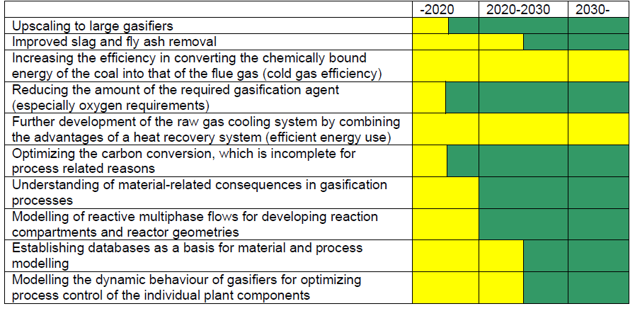
- Upscaling to large gasifiers (1200-1500 MWth) for single-train configuration with effective heat recovery / quench system and with low metal corrosion.
- Improved gasifier slag and fly ash removal
- Increasing the efficiency in converting the chemically bound energy of the coal into that of the flue gas (cold gas efficiency)
R&D needs
- Upscaling to large gasifiers (1200-1500 MWth) for single-train configuration with effective heat recovery / quench system and with low metal corrosion.
- Improved gasifier slag and fly ash removal
- Increasing the efficiency in converting the chemically bound energy of the coal into that of the flue gas (cold gas efficiency)
- Reducing the amount of the required gasification agent (especially oxygen requirements)
- Further development of the raw gas cooling system by combining the advantages of a heat recovery system (efficient energy use)
- Optimizing the carbon conversion, which is incomplete for process related reasons
- Understanding of material-related consequences in gasification processes
- Modelling of reactive multiphase flows for developing reaction compartments and reactor geometries
- Establishing databases as a basis for material and process modelling
- Modelling the dynamic behaviour of gasifiers for optimizing process control of the individual plant components
Summary table: Gasification / Reforming
(Colour codes: Green – validated, Yellow – partly validated, Red – not validated)
2.4.3 CO shift
The water-gas shift (WGS) reactors are central in of many power production schemes. Simplified process schemes can be developed if highly active WGS catalysts working in the presence of significant amount of acid gases such as H2S and COS are developed. In addition, process schemes where CO2 capture is carried out in the WGS reactors, either by the use of sorbents or by the use of membranes, can be efficient alternatives to the conventional schemes. These are further dealt with under “Integrated components”.
Key challenges and long term R&D targets
- Develop improved WGS catalysts
- Develop highly active sour WGS catalysts.
R&D needs
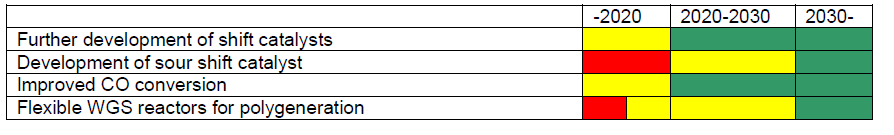
- Further development of shift catalysts (durability, cost reduction, admission of high CO concentration)
- Development of highly active and stable sour WGS catalysts
- Improve CO-conversion in order to reduce CO2 leakage from the overall power plant
- Flexible WGS reactors enabling polygeneration plants (electricity, hydrogen, synthetic fuels) allowing variations in their respective production share.
Summary table: CO shift
(Colour codes: Green – validated, Yellow – partly validated, Red – not validated)
2.4.4 CO2 capture in pre-combustion applications
In the common scheme, CO2 is captured at high pressure in a separate step after the low temperature watergas shift reactor. Physical solvents are the state-of-art technology for this step. Pressure swing adsorption (PSA) processes are an alternative. Other possible process concepts based on solid sorption or membranes integrated into catalytic processes are dealt with under “Integrated components” (2.4.6).
Key challenges and long term R&D targets
- Energy requirement of alternative physical solvent based separation processes
- Development of pressure swing adsorption (PSA) processes based on solid adsorbents. The challenge is to find good adsorbents with high cyclic capacity in the actual pressure range. Another challenge is to find adsorbents with high selectivity for CO2 in order to avoid accumulation of impurities that necessitate extra thermal regeneration of the adsorbent.
- Capture of CO2 at higher temperature to avoid cooling down step before combustion step
- Chemical stability and loss of solvent.
- Stability of adsorbent in the presence of contaminants such as H2S, etc
R&D needs
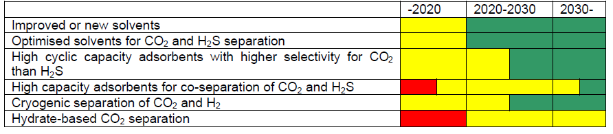
- Development of improved or new solvents for CO2 capture in pre-combustion applications
- Optimised solvents to separate CO2 and H2S
- Develop solid adsorbents that will adsorb CO2 with higher selectivity than H2S
- Develop solid adsorbents that can separate both CO2 and H2S in one step.
- Cryogenic separation of CO2 and H2
- Hydrate-based CO2 separation.
Summary table: CO2 capture in pre-combustion applications
(Colour codes: Green – validated, Yellow – partly validated, Red – not validated)
2.4.5 H2 gas turbine
In pre-combustion capture technologies there is a need for gas turbines that can operate on hydrogen-rich fuel gas with performance and emission levels that can match today’s modern gas turbines for natural gas.
Currently, gas turbines for hydrogen-rich fuels employ non-premixed burner technology using diluents such as N2 and H2O in order to keep flame temperature and NOx emissions down. Reduced turbine inlet
temperature in order to compensate higher moisture content and increased heat transfer is also used.
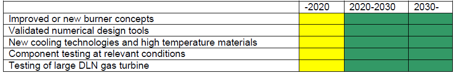
These drawbacks could be overcome by some kind of dry low NOx (DLN) for hydrogen-fired gas turbines. R&D is already ongoing on DLN combustors and gas turbines for hydrogen combustion, but more efforts are required.
Key challenges and long term R&D targets
- Dry Low NOx burner technology without the need for large amounts of diluents
- Burner concepts for better fuel flexibility and reliability
- Increased turbine inlet temperature for higher efficiency
R&D needs
- Improved or new burner concepts based on a low-emission mode of operation
- Validated numerical design tools including detailed resolution of the fuel / air mixing and combustion
- New GT cooling technologies, high temperature materials and hot path coatings
- Component testing and demonstration under relevant conditions.
- Testing of a large gas turbine in the scope of a demonstration plant
Summary table: H2 gas turbine
(Colour codes: Green – validated, Yellow – partly validated, Red – not validated)
2.4.6 Integrated components
Major simplifications of process schemes may be obtained by integration of components and/or material development. Typically by combining a sorbent or membrane into a catalytic process, the equilibrium of the process can be shifted drastically, thus making following separation and/or purification steps redundant.
Key challenges and long term R&D targets
- Reducing the size of equipment and increasing the conversion by combining reaction and separation in single units
- Making use of more advanced materials (membranes, sorbents, …) that will be a more integrated part of the process, not only being the shell.
- Material manufacturing methods and costs
- Cyclic capacity, stability and compatibility of sorbent at reaction conditions
- Flux and stability of membrane at reaction conditions
- Materials long-term stability and performance in harsh environment
R&D needs
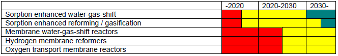
- Sorption enhanced reforming / gasification (SER): SER is based on the capture of CO2 in a gasification (reforming) reactor using sorbent particles to react with CO2 forming carbonate. Due to the capture of carbon the equilibrium is shifted towards H2. As a result gasification (reforming) and the shift reaction are done in one process step, typically at temperatures from 500 to 700°C and elevated pressure. The produced carbonate has to be calcined (regenerated) in a separate step. Most commonly used process design is an interconnected fluid bed reactor system. There are several experimental results with biomass published from laboratory scale prototypes (10-100s of kW) operating in continuous mode. The application to fossil fuels brings up concerns on conversion rate, in-situ sulphur capture, sorbent / catalyst durability, etc.
- Sorption enhanced water gas shift: In this high pressure process a sorbent is used to remove CO2 from the gas streams during the water-gas shift reaction shifting the equilibrium towards improved H2 yield and negligible rests of CO and CO2 in the effluent. The sorbent has to be regenerated in a separate step in a cyclic manner. As a consequence of the high pressure, PSA processes are most commonly envisaged, but TSA processes can also be considered. Major challenges are to find sorbents with high cyclic capacity and stability under the reaction conditions used (typically 200 to 450°C, 20-40 bar, high steam pressure) and to handle any H2S that is present.
- Membrane water gas shift reactors: In a similar manner as for sorbent enhanced water-gas shift, a hydrogen or carbon dioxide permeable membrane is used in situ to remove product gases during reaction, thus shifting the equilibrium towards higher conversions. Most challenging is to develop membranes with high flux, selectivity and stability at the relevant reaction conditions – temperatures from 200 to 450°C and elevated pressure.
- Hydrogen membrane reformers: In a similar manner as for sorbent enhanced reforming, a hydrogen permeable membrane is used in situ to remove hydrogen during reaction, thus shifting the = equilibrium towards higher natural gas conversions. Most challenging is to develop membranes with high flux and stability at the relevant reaction conditions – temperatures from 500 to 800°C and elevated pressure.
- Oxygen transport membrane reactors: OTM may find applications in large scale processes for oxygen production (air separation unit), for chemical production (syngas produced from autothermal reforming - ATR- or partial oxidation -POX) and for energy conversion (Coal to liquid, coal to gas, oxycombustion and IGCC processes). These processes require a very large quantity of O2 at high temperature (above 500°C) and pressure. The main challenges are to improve membrane integration by increasing the surface / volume ratio, to increase the membrane lifetime, and to scale up the manufacturing of membranes and modules while reducing costs.
Summary table: Integrated components
(Colour codes: Green – validated, Yellow – partly validated, Red – not validated)
2.4.7 Overall process development and integration
If the classical individual components and the overall IGCC concept are further optimized then electrical efficiencies above 50% without CO2 separation seem to be possible. Precondition for this improvement is a gasifier adapted to the IGCC concept and furthermore the development of gas cleaning processes that run at elevated temperatures and also, if possible, that operate in a dry mode. Additional potential for process optimization lies in the integration of an air separation unit, CO conversion and CO2 separation within the IGCC process.
In particular when targeting to integrate novel technologies (refer to section 2.4.6) with the purpose of improving the process performance, new challenges are likely to appear for the overall process development. As the knowledge of IGCC operation increases with the increasing number of plants, new possibilities for process integration will be easier to identify. IRCC plants (pre-combustion capture based on reforming of natural gas) currently appear to have a high power penalty, but their attractiveness may increase with the development of novel integrated components (refer to section 2.4.6). Hence, there may also be a need for overall process development and integration for this kind of power cycles with CO2 capture.
Key challenges and long term R&D targets
- Low availability
- Long start-up time
- Poor part load efficiency of IGCC
- Finding the best integration of novel (integrated) components for performance improvement
R&D needs
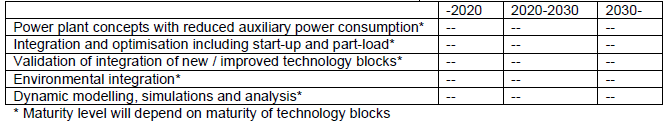
- Optimised power plant concepts with reduced auxiliary power consumption
- Overall process integration and optimisation incl. start-up and part-load aspects
- New / improved technology blocks will require subsequent validations of integration issues
- Environmental integration of the power plant with respect to e.g. cooling water requirements, liquid effluents and their purifications
- Development and implementation of dynamic models to study transients in the power process as well as in specific components
Summary table: Overall process development and integration.
(Colour codes: Green – validated, Yellow – partly validated, Red – not validated)
2.5 Technologies and research areas enabling improved CO2 capture performance
This section lists R&D topics connected to the technology blocks in table 1 that were not marked with bold letters and also other areas related to the performance improvement of power plants with CO2 capture beyond year 2020.
2.5.1 Advanced steam cycle technology
CCS technologies have a negative impact on the net efficiency of modern pulverised coal fired power plants. Consequently, an intelligent and cost effective use of CCS technologies requires new strategies to increase the net efficiency of these plants. Among them, the most promising are:
- Increase working steam temperature and pressure in new Ultra Super Critical (USC) power plants (up to and maybe beyond 350/370 bar, 700/750°C), and hence increase the severity of fireside operating conditions, as well as potential new internal oxidation damages and higher creep.
- Promote long-term efficiency increase in existing and next generation USC power plants, reducing / eliminating out-of-service accidents and introduce maintenance criteria based on provisional material component evolution models.
Key challenges and long term R&D targets
All the above mentioned technologies are scientifically viable but bring severe technological challenges in materials / components reliability, especially in terms of:
- Increased resistance of metallic components to creep and creep fatigue in complex thermo-mechanical conditions (e.g. non steady state working conditions),
- Increased resistance of ceramic components (e.g. refractory) to thermal shock and fatigue,
- Increased resistance of ceramic and metallic materials to oxidation / hot corrosion, erosion-abrasion and wear under increased operating pressure,
- Increasing knowledge of microstructure instability during service, as expected in high alloyed metallic materials and ceramic components operating under highly demanding environmental conditions (e.g. atmosphere composition, temperature, pressure, multi-axial strain-stress),
- Improved component design criteria, taking account of material response in service (e.g. thermal cycling stresses, high thermal expansion in austenitic steels and nickel-base alloys, differential behaviour at welds and joints),
- Improved inspection procedures and maintenance strategies, through a strong integration of field data from advanced sensor / monitoring systems and output from metallurgical physical-chemical and thermo mechanical models, in order to describe component behaviour during service and provide tools to assist plant operating decisions.
R&D needs
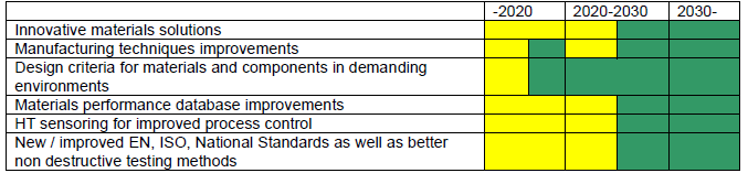
- Innovative solutions in material science (e.g. Fe-base and Ni-base materials, ceramics, coatings)
- Improvement of manufacturing techniques (melting, large forging / casting, rolling / extruding, welding, etc.)
- Improvements in design criteria of materials and components for application in very demanding environments (e.g. high temperature, hard fume composition, variable multi-axial load), through the integration and development of engineering + metallurgy evolution models and new experimental test procedures and configurations (e.g. creep-fatigue tests on pipes, including welds)
- Improvement of material performances databases by advanced experimental tests at medium scale and full-scale test loop(s) / rig(s)
- HT sensoring for improved Process Control
- Definition and promotion of new / improved EN, ISO and National Standards for the application of new engineering solutions as well as better non destructive testing methods.
Summary table : USC technology (700-750°C).
(Colour codes: Green – validated, Yellow – partly validated, Red – not validated)
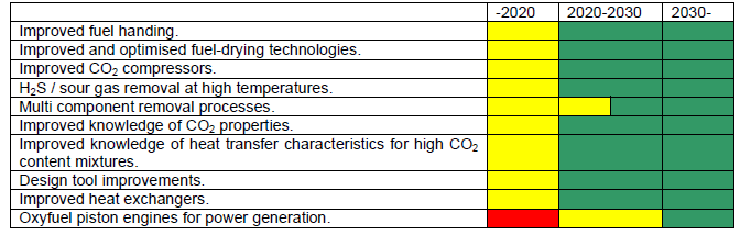
2.5.2 Other technology development
Ensuring cost effective CO2 capture processes requires improved knowledge and standards for processes, components and interdisciplinary areas not directly linked to the technology blocks in table 1. R&D needs related to such processes are listed below.
R&D needs
- Improved fuel handing, in particular fuel feed to pressurized systems, e.g. gasifiers.
- For fuels with high moisture contents, such as lignite, atmospheric and pressurised fluidised bed fuel drying technologies are developed and expected to be demonstrated in Period I. Further improved and optimised fuel-drying technologies, that could be efficiently integrated into power plants, could contribute to higher efficiencies.
- Improved CO2 compressors (robust, high efficiency, part load capability)
- H2S / sour gas removal at high temperatures. Precombustion methods of sour sources of fuels, results to sour gases. Development of processes for CO2 and H2S removal from reformed gases at high temperatures are required. Adsorption at high temperatures and membranes are possible candidates.
- Multi component removal processes. Simultaneous removal of H2S / CO2 / -Hg / dioxin / ….
- Improved knowledge of CO2 properties
- Improved knowledge of heat transfer characteristics for high CO2 content mixtures
- Design tool improvements: current process design tools are typically based on either chemical engineering or mechanical engineering principles, an interdisciplinary approach is needed.
- Improved heat exchangers.
- Oxyfuel piston engines for power generation
Summary table: Technology development
(Colour codes: Green – validated, Yellow – partly validated, Red – not validated)
2.5.3 System studies
In addition to process and component related R&D needs described above there is also a lack of knowledge within overall system related topics
R&D needs
- Investigation of total environmental footprint from different types of power generation with CO2 capture
- Research on operation of fleets of power plants with CO2 capture (connected to more than one infrastructure, electric power grid, CO2 network and possibly also H2 network. Today power plant operation is optimised with respect to daily power demand variations and what prices can be achieved. CO2 capture has to become a parameter in this so that the capture is optimised and balanced between short-term power demand variations and yearly CO2 quota. This kind of system analysis could partly be based on research on CO2 value chains
- Research on how to integrate CCS and fuel cells in energy systems: Fuel cells represent the most energy efficient power production, and the combination of fuel cells and CCS is an option worth investigating for reducing CO2 emissions. R&D are needed to optimize the integration of fuel cells and CCS
- Studies on large-scale vs small-scale CCS applications: On a long term perspective, small scale CCS could be commercially viable. Small scale power production with small scale CCS could represent a possibility for green power production for all the small villages in developing countries that do not have electricity today. Studies are required to compare technological and economic aspects of small scale and large scale CCS. Key challenges for realization are small-scale transport and storage of CO2.
- A research framework that enables tight integration between technology development on different scales and research areas; e.g. solvent-capture process-power process and membrane-membrane reactor power process. The purpose of such R&D should be to get good design targets for solvents or materials and the best possible integration in a dedicated power process.
3. CO2 transport and storage
3.1 Technology structure
The Table 3.1 below gives an overview of the main transport and storage routes and their anticipated level of maturity at different timeframes. Colour coding has the following meaning:
- Red Not validated: Not tested / Less advanced than pilot scale
- Yellow Partly validated: Ready for demo plant
- Green Fully validated: Commercially available.
Table 3.1. Overview of Transportation and Storage, anticipated level of maturity at different times.
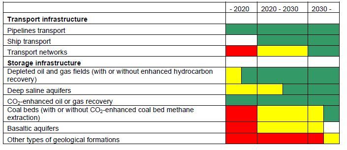
In the coming chapters, are described all the research areas needed to help develop these transport and storage options for being ready for wide-scale CCS implementation from 2020. The long term research targets presented in this document comprise improved and new approaches as well as innovative combinations of existing technologies and methodologies for CO2 storage. The themes presented cover the technologies and methodologies that relate to individual parts of the transport and storage value chain and the integrated system for clarity.
In terms of technologies the areas we expect developments are in: well drilling, injection and remediation; storage reservoir and geosphere monitoring; on-shore and off-shore environmental monitoring.
In terms of methods and methodologies we expect developments in: specific storage site selection and capacity estimation; reservoir management methods for pressure and fluid management; CO2 monitoring and modelling methods; risk evaluation; uncertainty management; and CO2 transport - storage integrated system management.
The standardisation of technologies, methods and methodologies used for CO2 transport and storage is considered essential for the widespread deployment of CCS.
3.2 CO2-related well technologies
Wells are necessary to gain access to the reservoir, both to inject CO2 and to characterise or monitor subsurface rocks and formation fluid properties. New wells should be designed carefully for long-term zonal isolation and instrumented according to purpose. Existing wells should be managed to avoid leakage.
Existing technologies to design, build, repair and abandon wells in oil and gas reservoirs appear to be broadly sufficient to guarantee safe, long-term CO2 storage. There is therefore no need for a revolutionary approach for well construction, maintenance and closure in CO2 environment, but rather for a natural evolutionary progress in the technology to improve well reliability over the life of a CO2 injection project.
Experience from oil and gas wells – especially those that have been exposed to CO2 either through production or through injection to improve hydrocarbon recovery – suggests that catastrophic leaks can be excluded except in cases of gross negligence.
However, it remains true that existing wells penetrating the storage reservoir (true in particular for depleted oil and gas field as opposed to deep saline formations) have to be considered as an important factor in the overall leakage risk. This is because it is difficult to estimate the long term reliability of wells given the relatively short time span of oil and gas exploration experience in the field and the knowledge gained from laboratory studies. Current lab experiments are limited in applicability since they generally consist in the immersion of cement samples in CO2-rich fluids, which is not representative of field conditions. Indeed, it is widely accepted, based on experience with oil and gas wells, that integrity is overwhelmingly lost through defects (e.g. micro fractures, debonding at interfaces), which, when connected, can create a leakage path.
Consequently, the next step is to adapt laboratory setups to better reproduce real conditions, develop transport-reaction models to explain experimental results carried out over a short period of time, and extend these models into ageing models in order to estimate the long-term durability of well material during CO2 injection or after abandonment. Such models should be used to develop methodologies to screen, evaluate and manage leakage risk for both old and new wells. Evaluating old wells is particularly important when well density is high (such as in early oil provinces) or when intervention cost is high (such as offshore).
Current technology development efforts also focus on the deployment of corrosion-resistant materials, such as chromium steel alloys and CO2-resistant cement systems. Some effort is also dedicated to testing the feasibility of truly inert materials as well as materials and methodologies to repair failed completions.
Completion technologies that enable to bypass damaged zones and improve injectivity also require additional research effort: drilling and stimulation techniques (e.g. multilateral drainholes or hydraulic fracturing), and injection techniques to ensure safe, reliable injection of cold or multiphase CO2.
A final set of techniques that require further research is leak monitoring, especially for methods to identify and characterise leaks in cemented wells (acoustic and thermal methods currently used are of uncertain precision and accuracy), and to monitor well integrity in real time (intelligent completions).
R&D actions (content / scope)
- Advance technology for drilling slim hole wells to explore the geology of potential CO2 storage formations and surrounding geosphere, to characterise the storage complex, and to monitor the storage complex
- Develop an understanding of the long-time behaviour of standard completions (cement, steel, elastomer) when exposed to CO2 lab protocols to screen and characterize completion materials.
- Develop fit-for-purpose drilling technologies for CO2 storage. In particular, develop new well materials (including composites) for better long-term resistance to CO2, impurities and saline brine attacks
- Develop technology for better leak detection, characterisation and repair
- Develop smart well completions with integrated monitoring sensors as a built-in components, which can be maintained over time
- Develop drilling or fracturing technologies specifically aimed at enhancing CO2 injectivity in sedimentary reservoirs, low-permeable coal deposits and ultra-basic rocks with high mineralization potential. This may include optimising schemes of up-dip or intersection drilling, such as in fish-bone configurations, fracking in near horizontal drillings, or accessing a coal sequence instead of coal seams for degassing and injection
- Develop technologies to monitor / re-work pre-existing wells that may be exposed to CO2
- Develop best-practice guidelines on CO2-related drilling
- Develop injection technologies to allow multi-phase injection or low-temperature CO2 injection without causing mechanical damage to well completion or reservoir and without requiring external heating
Expected impact
Better, cheaper and smart technologies for wells to enable collection of more and higher resolution information on the subsurface and to ensure well integrity, and to make more storage capacities available.
3.3 CO2 storage reservoir capacity assessment
To facilitate industrial-scale deployment of CCS beyond 2020, there is a need to evaluate storage capacity available for large-scale CO2 projects in various parts of the world and to demonstrate that very large quantities of CO2 (1–10 Mt/annum or more per project) can be safely stored. Whilst potential storage capacity in depleted hydrocarbon fields is relatively well understood through decades of oil and gas industry experience, the larger potential capacity in deep saline formations is subject to greater uncertainty due to the limited number of current demonstration projects.
Determination of storage capacity is a complex issue, heavily dependent on the scale of assessment and the level of technical, economic and regulatory factors taken into account. In order to address this complexity, several organisations have developed CO2 storage classification schemes. An example is the technoeconomic resource-reserve pyramid proposed by the Carbon Sequestration Leadership Forum (CSLF) in 2007, which was used to frame storage capacity assessment in the recent EU Geocapacity project. In simple terms, the CSLF scheme defines theoretical capacity as the maximum total pore volume that could be available for storage, effective capacity as a subset of theoretical capacity after technical factors have been applied, practical capacity as a subset of effective capacity after further technical and economic factors have been applied, and matched capacity as a subset of practical capacity where storage potential is linked to suitable anthropogenic sources of CO2.
Assessment of theoretical or effective storage capacities can be made using analytical methods and is appropriate for ‘high-level’ regional assessments. Theoretical capacities can be converted to effective capacities by applying a storage coefficient (also termed the efficiency factor). Subsurface modelling studies have established values for this coefficient for differing scales of assessment and various geological settings, however experience gained from future demonstration projects should allow refinement and verification of coefficient values.
Determination of practical capacity requires consideration of local operational and environmental constraints such as reservoir injectivity and pressure limits, seismic activity, existing wells, competition with other uses of the underground, protected areas, etc.; while for matched capacity, CO2 transport infrastructure and supply rates need to be considered.
Whilst many capacity assessments to date have focused on the demonstrated storage options of depleted hydrocarbon fields and deep saline aquifers, alternative scenarios such as enhanced coal bed methane (ECBM), ultramafic or basaltic rocks and complex sedimentary sequences are also being researched; capacity assessment methodologies may need to be developed as confidence increases in these alternatives as viable technical options.
R&D actions (content / scope)
- Develop and refine storage coefficients for estimation of effective storage resources at regional scales, especially for deep saline aquifers;
- Develop methodological standards to determine practical and matched capacities at local scales,
especially for deep saline aquifers; - Expand evaluation methodologies as necessary to cover alternative storage scenarios such as ECBM, complex sedimentary geology, coal sequences, basalts, ultramafic rocks;
- Develop and refine regional capacity assessments for all EU countries and developing nations where CCS needs to be deployed, including publication of a European storage / CCS atlas.
Expected impact
Robust methodologies that can be used to quantify available storage options at a variety of scales, especially in regions and geological settings with currently unclear storage potential, that will benefit from experience gained by early demonstration projects. This will be a key requirement for enabling operators and policy makers to plan implementation of CCS.
3.4 Modelling the storage reservoir and geosphere
Modelling of the storage reservoir and geosphere is recognised as being essential in CO2 storage projects' development:
- for predicting storage capacity, injectivity, CO2 plume evolution and trapping phases, caprock integrity, potential leakage through wells and faults, and ground stability;
- for informing the risk assessment process;
- for designing monitoring programmes.
The EC Directive 2009/31/EC on the geological storage of carbon dioxide describes the modelling requirements, including the collection of data, the construction of a 3D static geological earth model, the implementation of dynamic modelling, and the assessment of sensitivity and the uncertainties associated to model parameters and assumptions. Over time, from the early project planning to post-closure, an iterative procedure needs to be established, whereby comparison of monitoring and modelling results enables to improve both models and monitoring plans, until sufficient agreement between observed and predicted storage behaviour is reached.
Research activities during the last decade led to significant progress on modelling issues, which enable now to support a range of storage demonstration projects. Modelling of key processes has been developed: multiphase flow, geochemistry and reactive-transport, geomechanics, and heat transfer. The coupling of several of these processes has been initiated. Different compartments of the storage system have been modelled including the storage reservoir, caprock, well, fault, and overburden covering different spatial scales and time scales, e.g. the short-term processes occurring around the injection well and the long-term processes occurring in the whole storage complex. Benchmarking of models with lab experiments and field data from pioneering projects has been carried out when possible.
However, in order to support the widespread industrial deployment of CCS, considerable development work is considered essential before modelling approaches can be used to describe storage behaviour with a sufficient level of confidence. Methodologies and tools for coupling key processes will need to be further developed, as well as our understanding of coupling effects and competing timescales of the various processes. Similar efforts should be undertaken for the upscaling of properties and processes from pore to field scale. Linking the various compartments is needed in order to have a comprehensive understanding of the whole system. The methods that may be used to handle the natural heterogeneities of the geological media will have to be resolved. In addition CO2 streams of different qualities / compositions need to be considered. Benchmarking of models with lab and field data will need to be strengthened. Finally, modelling standards and guidance documents for practitioners and non-specialists stakeholders need to be developed.
R&D actions (content / scope)
- Develop coupled / multi-physics models including flow, geomechanics, geochemistry, and thermal
effects to predict the fate of CO2 and associated components in the subsurface, as well as the storage dynamic behaviour with time. - Develop multi-scale modelling methods and upscaling methodologies. Take into consideration the
heterogeneities of the geological media. Use forward depositional modelling. - Progress batch and core flooding experiments on rock-fluid interactions for reservoirs and seals to provide input parameters and benchmarking cases to modelling. Therefore develop fit-for-purpose experiments with advanced characterisation and measurement techniques to further develop knowledge on CO2 trapping mechanisms, CO2 dissolution in formation waters, reactional pathways for mineral dissolution and precipitation, transport properties, role of heterogeneities, and effect of additional components (H2, CH4, N2, O2, SO2…). Develop also methodologies for integrating experimental results into realistic field-scale schemes.
- Develop specific dynamic models for sensitive zones such as the near well area and faults. Integrate reservoir / compartment modelling with full system modelling of the surrounding geosphere.
- Develop fast / systemic models for sensitivity and uncertainty analysis.
- Develop improved modelling tools to facilitate and automate history matching with field observations. In particular, develop multi-physics multi-resolution inversion techniques for model calibration (history matching) and monitoring plan optimization.
- Develop agreed standards for modelling and guidance documents for practitioners and regulators.
Expected impact
Advanced modelling techniques for higher confidence in predicting storage performance from short to long term periods.
3.5 Monitoring the storage reservoir and geosphere
Large scale projects both on- and off-shore such as Weyburn, Sleipner, In Salah, Snøhvit, have
demonstrated that monitoring technologies are actually available to fulfil the requirements of the Directive 2009/31/EC on the geological storage of carbon dioxide, regarding the behaviour of the injection infrastructures and the fate of injected CO2 in the storage complex. Studies and experiments performed at sites, where CO2 naturally leaks, have allowed to understand, model and measure the behaviour of CO2 in the near subsurface and at the surface, both on land and at the sea bottom. The results achieved until now are a valuable base to upgrade monitoring technologies and methodologies that have to be deep-focussed (for the reservoir and surrounding geological formations) and shallow / surface focussed.
Their aim is to (a) image / measure CO2 in the reservoir; (b) show that the site is currently performing as expected; (c) provide data for modelling the effects of CO2 storage at large scale (in the reservoir and in the surroundings area, also for evaluating potential effects on other activities, i.e. hydrocarbons exploitation and use of drinking water); (d) continuously control at affordable costs large areas in order to provide early alerts for focussed monitoring or remediation actions; (e) detect CO2 concentrations at the surface only slightly above the background level and at low leakage rate; (f) quantify eventual leakages at land and offshore to verify emission trading contracts and environmental impacts; (g) enable site closure; (h) define monitoring protocols for baselines definitions, injection and post-injection phases.
In this context, offshore monitoring is very challenging for operative difficulties and because the detection and quantification of eventual CO2 leakages require a complex model approach involving the physical and biological components in the sediments, at the sea bottom and above. Furthermore, it has to be stressed that the selection of monitoring techniques will always be subject to site-specific circumstances. Due to that, we need to improve and to test them in a large variety of geological contexts, in order to extend their use and to validate the more effective ones.
R&D actions (content / scope)
- Improve the precision and detection level of leakage monitoring technologies in different subsurface layers and at the surface to allow early and effective remediation, in on-shore and off-shore settings
- Develop non-intrusive, passive and long term monitoring methods
- Develop high-level agreed standards for on-shore and off-shore monitoring
- Develop methodologies to establish monitoring requirements during the CO2 storage project planning, operation, closure and post-closure periods
- Investigate technologies and methodologies for leakage quantification offshore and onshore
Expected impact
Advanced monitoring techniques and methodologies for early, cheap and reliable identification of leakages or significant irregularities. Acceptance of monitoring systems into the Monitoring and Reporting Guidelines for CCS within the EU ETS.
3.6 Management of the CO2 storage complex
The management of the storage complex during the injection period consists in optimizing, in a cost-effective way, the storage performance in terms of capacity, injectivity and containment while controlling risks to avoid any adverse effects on people or the environment. Injection patterns will have to be carefully designed and optimized at the field level, both in time and space, to accommodate with the characteristics of the delivered CO2 stream.
Storage capacity may be strongly affected by formation heterogeneities, compartmentalization, or more generally the confined / unconfined characteristics of the targeted formation. In saline aquifers especially, the low water compressibility may lead to a very low available storage volume, with the possible need to produce water out of the reservoir to create more space. Maximizing the volume of CO2 stored thus imply managing carefully the pressure distribution as well as the movement of fluids in the storage complex.
Injectivity can be affected by near wellbore effects induced by the gas-stream injection, such as precipitation of solids (salts), or dissolution of minerals (in carbonate reservoirs). These effects, which depend on the gas stream composition and the geochemical properties of the reservoir rock and brine, are not well characterized today, for instance the impact on rock permeability. Careful well design, stimulation techniques or other formation treatments may be necessary to maintain the desired rate of injection. Such procedures have been developed by the Oil & Gas industry but will have to be adapted to the context of CO2 storage
CO2 containment needs to be carefully managed during the injection period:
- The integrity of the main barriers (cap rocks, faults, and wells) should always be maintained. In particular transient injection operations that could compromise the integrity of the cement sheet should be avoided.
- The efficiency of trapping mechanisms should be maximized, in particular dissolution and mineralization.
- The migration of CO2 plume inside the storage complex should be controlled and reported.
Such objectives will be met through appropriate design, day-to-day control and adjustments of injection operations, using methodologies which are not well identified today. Should an integrity loss or even a leak occur, appropriate mitigation measures will have to be taken to restore the sealing capacity of the barriers and control any undesirable impact, which is discussed in section 3.8 on “Remediation and Mitigation”.
In summary, although CO2 storage is expected to be further demonstrated at commercial scale by 2020, the following R&D actions will be necessary to allow the widespread deployment of the technology beyond 2020 by improving and standardising storage complex management procedures in order to maintain efficiency and safety.
R&D actions (content / scope)
- Develop smart techniques for managing fluid movement and pressure in the reservoir (injection /
extraction of water, use of gel / foams, etc.) - Address injectivity issues for large CO2 quantities and associated impurities, and the effects of rapid transient injection operation, with flow dynamics in the injection well and near well reservoir
- Develop injectivity guidelines for preventing any physical or chemical adverse effects around the wellbore that may compromise the injection of the desired quantities of CO2.
- Develop knowledge on the thermodynamics and kinetics of CO2, H2, CH4, N2, SO2 etc. mixtures
- Develop technologies to favour dissolution and in situ mineralisation (including catalysis)
- Evaluate the impact of deep biological activity on storage performance
- Develop methodologies to optimally manage the injection of several different CO2 streams during the lifetime of a storage site
- Develop integrated methods for CO2 storage performance assessment and management
- Improve procedures and develop standards for the day-to-day management of the storage complex during the injection period in order to maintain efficiency and safety.
Expected impact
Optimisation of storage performance in terms of capacity, injectivity and integrity by smart operational management of the storage complex during the injection period.
3.7 Assessment of environmental impacts
Assessing the environment impact of a potential leak is required by EU regulations (CCS and EIA directives), although the level of detail of such assessment is not specified and may go from a purely qualitative evaluation of impacts to a more quantitative analysis. This level of detail required for impact assessment will partly depend on site-specific circumstances, e.g. the sensitivity of potential receptors for any given storage site. There is a need for further research into the potential effects and quantification of CO2 and co-mobilised substances so that related technologies and methodologies can be developed, validated and deployed on site, with an estimation of associated costs. Technologies include (1) measurement techniques for site characterization; (2) monitoring techniques for leak detection and evaluation of possible impacts on the ecosystem, and (3) modeling tools for predicting system behavior and impacts on specific targets.
Characteristics and extent of impacts that may result from the potential leakage of CO2 need to be assessed and they will be dependent on the storage site and potential targets. The broad division will be between marine / sub-seabed and terrestrial sites; each will require their own assessment methodology and technology. For terrestrial sites the local surface geology and soil characteristics will be important determinants for the impact, coupled with the inventory of local flora and fauna on the ground and in the surface waters and groundwater. On the seabed, the seafloor characteristics will be important determinants together with the local marine ecosystem and ambient seawater. Finally, impacts will have to be scaled with respect to severity, and acceptable thresholds defined.
As storage sites will have a significant (10 km scale) horizontal extent, with leaks that may follow horizontal pathways radiating from the site, both large aerial extend and high sensitivity at specific locations will be important components of a robust and effective monitoring system. Remote sensing and autonomous sampling technologies seem to be the most promising and need to be developed further in order to specifically suit the tasks. This is about sensors, signal transmission, data processing and alert systems.
Industry considers Environmental Impact Assessment as a key component of the risk management process, but also recognizes the need for building experience and for extrapolating lessons from specific research before standards can be established. In particular, public databases are currently lacking, on both analogues and on experimental sites. Guidelines documenting monitoring techniques performances and protocols are also missing.
Regulators request such analysis in their process to qualify a site and grant permits. Procedures and decision tools should be developed to assist them in the process of evaluating the EIA documents submitted.
Finally, public, and specifically local interest groups will likely request to be involved in the process and be informed about possible risks. An early communication about EIA will be essential to obtain public confidence in the technology.
R&D actions (content / scope)
- Investigate into the fate of CO2 (and mobilised substances) in the subsurface and near surface environment and its influence on groundwater quality and local ecosystems in case of leakage, for both terrestrial and marine settings
- Develop monitoring techniques for specific issues, in particular remote-sensing techniques for early
detection and wide scale evaluation of potential environmental impacts from CO2 storage, and infrastructure development - Formation of databases for natural analogues and experimental sites, including interpretation of data and figures
Expected impact
More confidence on the near-zero impact on the environment, better acceptance.
3.8 Mitigation and remediation
The EC directive on the geological storage of CO2 establishes the obligation on the operator to take corrective measures in case of significant irregularities or leakages, on the basis of a corrective measures plan submitted to and approved by the competent national authority. The operator also has the obligation to assess the effectiveness of any corrective measures taken.
Such corrective measures mainly stem from the past efforts in the field of:
- Oil and gas industry, in particular natural gas storage activities;
- Wellbore integrity engineering;
- Pollution engineering, as CO2 leakage plumes show, in particular, similarities to volatile organic compound vapour plumes.
At wellbores, conventional procedures to correct potential irregularities in the structure integrity remain, to some extent, well-established at an engineering level, but still require to be validated considering the specificity of long term storage of CO2. In the geological domain, interventions practices based on reservoir and pollution engineering methods to correct significant irregularities, such as CO2 leakage or abnormal fluid displacement, still require further developments regarding the uniqueness of CO2 geological storage activities, whether it is in terms of time scale (from decades to centuries), or of large spatial scale impact (up to the geological basin scale), and also of the properties of the injected CO2 stream (buoyancy effect, geochemical reactivity, presence of potential impurities).
In this context, further research efforts should be undertaken to demonstrate if such corrective and remediation methods can be technically adapted, and above all, cost effectively used, at the injection, post-injection and post-closure phases of the storage project.
Mitigation and remediation rely on a robust monitoring so that any deviation from predicted behaviour can be detected so early that it can be assessed whether this deviation can be stopped by simply adjusting the operational management of the storage complex or requires deploying corrective measures. The sooner these corrective measures can be effectively executed, the better they will prevent any significant escape to the atmosphere or damage to the local environment. Focussed and repeated monitoring at targeted locations will be needed to support decision-making and control the efficiency of the measures taken.
Before CCS is widely deployed, it is important to develop best-practice guidelines informing regulators and site operators on the portfolio of various measures that can be used to remediate significant irregularities and leakages at different time-scales, both during injection and post-injection. Such guidance should include a documentation of the tested methodologies and an accompanying recommendation report.
R&D actions (content / scope)
- Adapt and extend the portfolio of remediation measures that can be rapidly applied to a broad spectrum of undesired movements and events
- Specifically develop remediation techniques (foam / gel, etc.) to maintain or/and restore sealing efficiency for both wells and geological system (faults & fractures)
- Develop methodologies for early remediation of any adverse effects from CO2 leakage on ground movement or the environment, including humans, ecosystems, groundwaters and soils.
- Study techniques that can be used to divert CO2 migration pathways from undesired zones
- Develop methods to alleviate excessive reservoir pressure that may compromise the sealing structures.
Expected impact
Provide safe storage also in case of undesired movements CO2 migration trends and events.
3.9 Land planning and transport infrastructure
To tackle the challenges of CCS technology much of the concern has focused on the capture technology and on the risks of leakage from potential storage locations. Nevertheless new know-how and requirements, validated by demonstration projects, are required in order to define and structure large scale CO2 transportation networks and integrate CCS schemes into land planning strategies.
The characterisation, assessment and permitting of a storage complex should be precautionary and existing equity interests, mineral and groundwater resources need to be fully protected. The site selection for CO2 storage and the design of the transport network should therefore consider:
- Proximity to the potential CO2 source(s) including estimates of the total potential mass of CO2 economically available for storage;
- Proximity and possible interactions with other activities (e.g. exploration, production and storage of hydrocarbons, geothermal use of aquifers, groundwater production, radioactive / hazardous waste disposal);
- Population distribution and protected habitats in the region overlying the storage complex and in the vicinity of the transport network;
- Consideration of potential trans-boundary transport issues.
Considering the very high number of CO2 source and sink clusters, the wide implementation of CCS technology across Europe requires significant efforts to develop an infrastructure network (pipelines, interconnection / injection stations). These efforts include defining regulatory models, consolidating design and operating guidelines and establishing standards which currently do not exist for the CO2 transport network.
The EU project ACCSEPT represents a step towards the responsible implementation of CCS in the EU region and the identification of existing gaps in socio-economic terms. On the other hand, a wide scale utilisation of CO2 sinks will require a different approach to land use management. It will be necessary to develop appropriate methodologies, standards and international regulations that can be used to control the exploitation of the subsurface and to avoid disputes or conflicts.
Technically, CO2 can be transported through pipelines or pressurised vessels in the form of a gas, a dense fluid or in the sub-cooled liquid state. Pipeline transport is expected to be the more promising means of transport where long distances must be covered and for significant quantities of CO2 . Despite the fact that CO2 transportation has not been extensively applied in Europe to date, it is technically feasible, if related design, contraction, operational guidelines and standards become available in the near future. It is worth noting that a 153 km, cross section 0.2 m subsea pipeline was put in service for dense phase CO2 in spring 2008 at the Snohvit field, offshore Northern Norway.
Around the world, more than 3000 km of pipelines (mainly in USA) transport approximately 50 million tonnes of CO2 per day for Enhanced Oil Recovery (CO2-EOR). These pipelines transport pure CO2 as a supercritical fluid or liquid (i.e. CO2 is kept in the dense phase at temperatures higher than "60°C and pressures above 73.8 bar) to meet operational and cost requirements. Whilst the CO2 transportation networks in America tend to transport near pure CO2, in the wide scale implementation plan for CCS in Europe, the CO2 stream captured from power stations and other industrial activities will contain minor amounts of other substances.
Further research is needed to verify that the dehydration of the CO2 stream can prevent corrosion whatever the level of other substances is, and that these substances in the CO2 stream do not have additional metallurgical and safety implications for the design of pipelines for CCS in Europe. Furthermore, CO2 transportation in Europe will generally be conducted across populated regions, which by its very nature will have necessary design implications.
As the experience in high pressure pipeline transportation of dense near pure CO2 (containing minor amounts of other substances) is very limited, current pipeline standards do not cover the transport of CO2 from a power production and CO2 capture plant to a suitable storage site.
R&D actions (content / scope)
- Consolidate site selection methodologies for the surface and network infrastructures.
- Develop materials and safety standards for CO2 transport considering impurities, taking into account overall CCS-chain limitations and impacts from mixing different gas qualities.
- Develop schemes with several sources – several sinks and logistics on how to handle and transport CO2.
- Develop methodologies and technologies to integrate plant-capture-transport-storage into an optimised integrated system considering operational, environmental and economic considerations over time.
- Investigate the possibilities for combined uses or conflicts with regard to other human activities on the earth’s surface onshore and off shore (e.g. gas storage, hydrocarbon production, geothermal energy, groundwater production, radioactive / hazardous waste disposal, etc).
- Address international issues, including cross-border transport and storage schemes that integrate countries with limited storage options.
Expected impact
Regional / National / EU coordination across the whole CCS chain for appropriate land planning and infrastructure development.
4. Other technologies for CO2 emission avoidance
4.1 Ex-situ mineral carbonation
CO2 can be reacted with magnesium and calcium silicate deposits, or with solid or liquid wastes, forming the corresponding carbonates and a solid by-product, e.g. silica. The carbonation reaction is exothermic and can theoretically yield energy that can be integrated with the capture process. Ex situ mineral carbonation could thus constitute a niche solution that would help cut down on CO2 emissions from certain industrial sectors.
However, the kinetics of natural mineral carbonation is slow; hence all currently implemented processes require energy intensive preparation of the solid reactants to achieve affordable conversion rates and/or additives that must be regenerated and recycled using external energy sources. Altogether, the technology is still in an early development stage and requires more R&D effort. Main R&D activities should be related to improving the kinetics of mineralization. Mineral carbonation could be suitable for small-scale CO2 sources as a complement to geological storage.
4.2 Chemical utilization of CO2
The conversion of CO2 into value-added chemicals is a highly relevant research topic for two reasons. One, use of CO2 as the primary C1 reagent in chemical synthesis strongly contributes to the development of sustainable chemistry, through the replacement of other toxic and non-renewable C1 sources such as phosgene and CO. Second, conversion of CO2 into chemicals is a short- to medium-term complement to geological storage of CO2, and this can also be (at least a partial) solution for remote or integrated CO2 emissions sources. Conversion of CO2 is also the only general route for reducing the costs associated with the CCS schemes for large CO2 point sources.
Note that CO2 conversion into chemicals is not a viable, large-scale CCS alternative, because the amounts of CO2 are too large for the chemical market to handle, even if CO2 is reduced to fuels. Large scale CO2 reduction is also problematic with regard to the overall CO2 budget if a non-renewable source of H2 is used (e.g. reduction of CO2 to methanol).
4.3 Biofixation of CO2
CO2 may be fixed biologically in living organisms and algae have a particularly high potential for this application. Biofixation of CO2 by algae thereby represents a future option for reducing atmospheric CO2 levels, although it should be noted that biofixation of CO2 in algae is not a permanent storage (i.e. removal from the atmosphere) of CO2. It is a reduction method only if the algae substitutes fossil fuels. A main R&D gap is to establish optimum algae growth conditions (temperature, water content, nutrients) for maximizing the CO2 uptake by the algae.
Characterization of species (there exists hundreds of thousands of varieties) for macro- and microalgae is also required. Furthermore, improved design of photobioreactors where the CO2 is captured by the algae is also required. Technology for large scale production and harvesting of macro algae are validated today and future R&D will focus on efficiency improvements to reduce cost. Micro algae face special R&D needs like development of efficient methods for harvesting and dewatering and improvement of technologies for separation of oil. Algae also face the challenges of large area requirement, slow kinetics and growth depending on weather conditions. Because of the latter they are best suited for fossil power plants located in southern Europe.
Area requirement can be solved by the fact that algae can be grown in closed systems on low value land, like deserts, but closed systems are also suitable for not so warm countries (intensive research is happening in countries like Germany and others) An important challenge is the up-scaling of proved culture techniques and species. Another challenge is to spread the focus from fuel to cover also other valuable compounds (protein, pigments, PUFA’s) through a biorefinery approach, to obtain an economic process.
With dedicated research, algae production for biofixation of CO2 could be a commercial technology during period II (between 2020 and 2030).
For what concerns the use of non-photosynthetic microorganisms to fix the CO2 emitted by fossil power plants, the research is still at a very premature level so it is to be considered a long term technology for period III (beyond 2030).
4.4 Combining CCS with biomass
CCS for power plants (boiler or gasification based) fuelled by biomass is a possible future technology with potential for becoming carbon negative. Recent studies indicate that such technology will be a must in order to achieve the targets for maximum temperature increase. If the development of optimised and cost effective biomass production is achieved, some variants of this technology could be ready at the latest during period II.
5. Overall summary and recommendations
R&D in identified areas must be initiated and/or continued now and in the years to come in order to reach estimated maturity at the defined time-scales; considering the time steps of development (laboratory – pilot plants – semi industrial – industrial – pre-commercial) continuity from the EU in supporting developing technologies is essential. In this context it is important to recognize the need for medium sized pilot plants – which are risky and costly – and which are a limiting factor of new developments. For technologies still at an early stage, correct technology potential assessment may be difficult, because “showstoppers” and sudden technology breakthroughs cannot be foreseen, but are the outcome of dedicated R&D.
Chapter 2 of his document is a compilation of identified long-term perspective R&D needs for the CO2 capture technologies known today. Novel technologies or novel use of known technologies for CO2 capture are however not unlikely to be presented in the years to come. It is therefore vital that future research programmes are formulated in such a way as to ascertain that these novel technologies can be included in the overall R&D programmes on CO2 capture and thus be given a fair evaluation. Novel technologies must not have for only advantage that they are advanced and innovative, but must have a potential for improvements compared to first generation CO2 capture technologies primarily in terms of cost and efficiency.
Storage is an essential component of the CCS chain and provides critical considerations in the CCS decision-making process and planning. The experience and knowledge generated through the existing and planned demonstration projects until 2020 will serve to inform decisions and reflect upon the technologies and methodologies proposed.
The standardisation of technologies and procedures / methodologies developed for CO2 transport and storage is considered essential for the widespread deployment of CCS.